
Download Autodesk Inventor Pro 2027 (x64) Full Version for Free, a 3D mechanical design software for creating parts, assemblies, and manufacturing drawings all in one, complete with an AI assistant to help repetitive tasks finish faster.
Overview of Inventor Pro 2027
Autodesk Inventor Pro 2027 is a 3D mechanical engineering design software from Autodesk used by engineers and designers to create everything from single parts to entire machinery systems. This software operates on a parametric concept, meaning the dimensions, shapes, and relationships of parts are tied together by variables and conditions. When a user modifies a single dimension value, the related parts adjust accordingly without requiring a complete redraw. This approach significantly reduces repetitive work and makes adapting designs to customer requirements or specification changes much faster.
Inventor's main strength lies in assembly design. Users can bring hundreds of parts together, define attachment points, axes of rotation, and motion constraints, and test whether the machinery moves as designed. The software alerts users when parts collide or interfere, revealing problems before actual manufacturing. It also features specialized tools such as sheet metal design that unfolds into flat patterns for cutting and bending, structural steel design that builds frames from standard profiles, pipe and wire routing within assemblies, as well as mold and plastic part design.
Once the 3D design is complete, Inventor automatically generates 2D drawings with dimensions, machining symbols, and parts lists according to engineering standards. The data in the drawing is linked to the original model; if the model changes, the drawing updates accordingly, reducing the risk of discrepancies between the drawing and the actual part. Built-in analysis tools allow engineers to test part strength before manufacturing, such as simulating pressure, tension, and torsion to see where parts might deform or break.
Inventor Pro 2027 is therefore suitable for designing machinery, industrial equipment, automotive and aerospace parts, as well as products that require assembly from numerous components. The software integrates well with other Autodesk tools, such as bringing designs from AutoCAD for further use, or sending data for drawing document management with Vault, allowing the design and manufacturing teams to use the same dataset from start to finish.
Who is this program suitable for?
Mechanical engineers and product designers who routinely model 3D parts will make the most of this, as tools ranging from sketching to manufacturing drafting are complete in one place. Teams working with sheet metal or steel structures have dedicated tools to support them without needing extra plug-ins, while factories that need to check stress or motion before actual production can use Stress Analysis and Dynamic Simulation beforehand.
How does Autodesk Inventor Pro differ from AutoCAD?
AutoCAD is a drafting software whose main job is drawing 2D lines and drafting, whereas Inventor Pro is a 3D mechanical design software whose main job is parametric modeling of parts and assemblies where editing dimensions updates the entire set. Inventor also features specialized tools that AutoCAD lacks, including sheet metal and steel structure capabilities, and the ability to simulate stress before actual production. However, both can open each other's DWG files, and Inventor can also use DWG files as a base to sketch 3D models.
Key features
Part design and assembly
- Parametric modeling. Define dimensions and conditions for sketches, and the model will adjust every time parameter values are modified.
- Assembly modeling. Assemble parts together, check for component collisions, and see if the assembly moves as designed.
- Direct modeling. Push, pull, rotate, or scale features directly from imported parts without having to go back and edit sketches.
- Freeform modeling. Sculpt freeform shapes by moving points, edges, and faces of the model.
- Patterning. Pattern features or parts in linear or circular arrays faster, with options for irregular spacing and directional control.
- Simplify. Cut unnecessary parts and features to create a simplified model, applicable to both parts and assemblies.
- Slot feature. Create grooves quickly with the new properties panel, and select sizes directly from the fastener library.
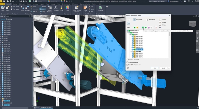
- Associative mirror. Mirrored parts remain linked in position and geometry to the master; edit the master and the mirrored side updates accordingly.
- Mechanical concept and layout design. Open DWG files directly and use them as a base to sketch 3D models.
Specialized mechanical engineering tools.
- Automated frame design. Create welded steel frames using automated tools and simulate forces with beam elements.
- Sheet metal. Design sheet metal parts, calculate bend allowances according to industry standards, and flatten them into a flat pattern for manufacturing.
- Tube and pipe design. Route pipes and hoses in assemblies using automated tools mixed with manual point-by-point control.
- Component generators and calculators. Calculate standard components such as welds, clamps, and press fits with built-in calculators.
- Shape Generator. Identify high-stress or low-stress areas in 3D models and optimize the geometry to be lighter while maintaining strength.
- Content center. Select standard parts from the library, including beams, bolted joints, gears, cams, belts, and springs.
- Model state. Create manufacturing states, simplification levels, and other variables within a single part or assembly file.
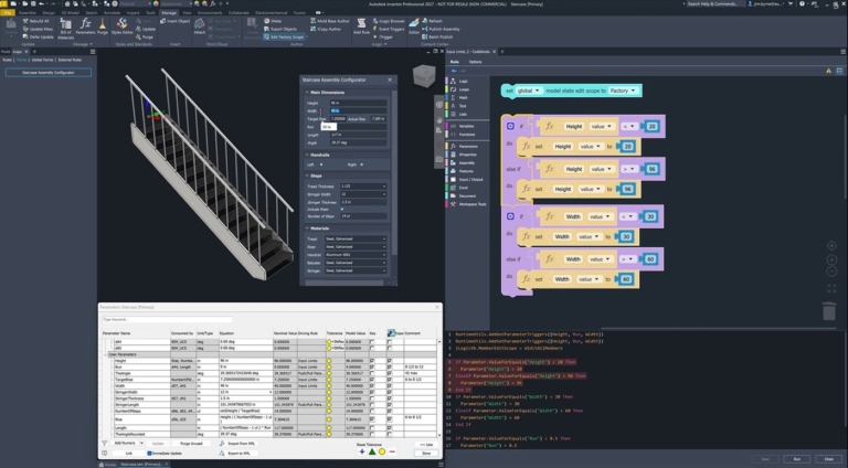
- Design configurations. Use customizable forms to generate new designs from engineering knowledge, driven by iLogic.
Analysis and Simulation
- Dynamic simulation. Apply forces and observe the motion, velocity, and acceleration of components.
- Stress analysis. Perform quick stress checks on parts or detailed analyses of entire assemblies at every step.
Drafting and Manufacturing Documentation
- Drawing creation. Place views and annotations onto production drawings quickly in both Inventor and AutoCAD.
- Model-based definition. Add dimensions, annotations, and tolerances directly to 3D models to pass on to the next stages.
- Weld symbol. Create weld symbols and sub-welds tied to the drawing and include them when exporting to 3D PDF, DWF, and Shared Views.
- Edge symbol. Add ISO-standard edge symbols and adjust their display properties from the properties panel.
- Finish utility. Specify surface textures and manufacturing processes, such as coating or finishing of the workpiece.
- Exploded views and animations. Create exploded views and animations for assembly manuals and product documentation.
Collaborate with teams and other software.
- Shared view collaboration. Share designs via secure web links; view, mark up, and comment from any device.
- Work with non-native data. Open 3D models from other CAD software while maintaining associativity with the original files.
- BIM interoperability. Create simplified 3D models with product data and categories for use in BIM projects.
- Fusion interoperability. Enable fast workflows between Inventor and Fusion, including generative design, simulation, electronics, and manufacturing.
- Revit data exchange enhancements. Exchange data with Revit more securely, connecting BIM and mechanical workflows.
- Informed Design for Inventor. Create parametric models, define BIM content and product rules, and share them with building design teams via the cloud.
- Printed circuit board interoperability. Combine electronic and mechanical designs into a single product definition.
- Data management. Manage data, track revisions, and collaborate within teams faster.
AI and automation
- Autodesk Assistant. Built-in AI assistant to answer questions, recommend workflows, and help complete repetitive tasks faster.
- iLogic codeblocks. Create parametric models and automation using drag-and-drop blocks without writing code.
- Content Center enhancements. Publish entire assembly sets to the Content Center, not just single parts, complete with batch management tools.
- Assembly mirror. Mirror sub-assemblies and parts with complete sets of options, providing finer control over mirrored components.
What's new
Version 2027.2
- Autodesk Assistant. Better support for iLogic workflows with the ability to set event triggers, such as creating a rule to check iProperty values before saving files, and improved understanding of iComponents and Model States.
- Autodesk Assistant. Connects with external AI agents via a local MCP server, such as Cursor, Claude Code, or GitHub Copilot, allowing them to inspect and modify models in the active session.
- Autodesk Assistant. Attach files to provide context for questions, including images, spreadsheets, and PDFs, up to 5 files at a time.
- Assembly. Each constraint type has its own button on the Assemble tab, allowing constraints to be placed without selecting the type in the dialog first.
- Assembly. Tangent constraints allow multiple target components to be selected at once.
- Assembly. Hold Alt while hovering to display origin planes, axes, and points of components, and place bolts and washers simultaneously from a single selection.
- Assembly. The Mirror command features a redesigned interface that groups options for better clarity.
- Assembly. Place and Insert allows multiple constraint-bound components to be placed at once.
- Assembly. Model States can be created faster using the + button, support drag-and-drop hierarchy reordering, include arrows indicating where model states are delegated, and display warning icons for outdated files.
- Sketch. Add geometry to sketch patterns while editing features for both rectangular and circular patterns in parts and assemblies.
- Sketch. Dimensions between lines and tangent circles now support Flip Direction.
- Drawing. Dragging a drawing view updates connected views accordingly, and pressing Alt locks the movement direction.
- Drawing. When retrieving model annotations, there is an option to avoid re-pulling dimensions that have already been retrieved in other views.
- General. Typing a parameter name in a dimension field, property panel, dialog, or Equation column displays a list of matching names to choose from.
- General. Choose which tab the Open and Save As dialogs open to by default.
System Requirements
- Operating System: Windows 11 and Windows 10 (64-bit)
- Processor: 2.5 GHz or higher (3.0 GHz or higher, 4 cores or more, with AVX2 and AVX512 support recommended)
- Memory: 16 GB for assemblies with fewer than 500 components (32 GB or higher recommended)
- Disk Space: Approximately 40 GB
- Additional Requirements: 4 GB GPU with DirectX 11 support (8 GB or 16 GB with DirectX 12 support recommended), screen resolution of 1280×1024 (3840×2160 recommended), and .NET 10.0 or higher required.
file information
- Operating System: Windows 10 / 11 (64-bit)
- Risk Level: Medium
- License: Commercial
- Developer: Autodesk
- Language: English
- Size : 6.37 GB
- File type : *.rar
- Password: mawto
- Installation method: Yes
- Updated on: 15/11/2026
- Need to read: Download Guide
==== Main Link ====
==== Backup Link ====